I am going to design a circuit that uses a battery as a power source. And an adapter as the input power. So I need a circuit that switches the power source automatically from battery to input power. And I do not want to add a chip to do this because it will increase the cost of the board. The simple circuit for that could be: The shortcoming of this circuit is that it will consume some power by the diode D1 when the adapter plugs in. In order to overcome this, a P-MOSFET is used to replace it. The simulation showed it works well. I will test it later.
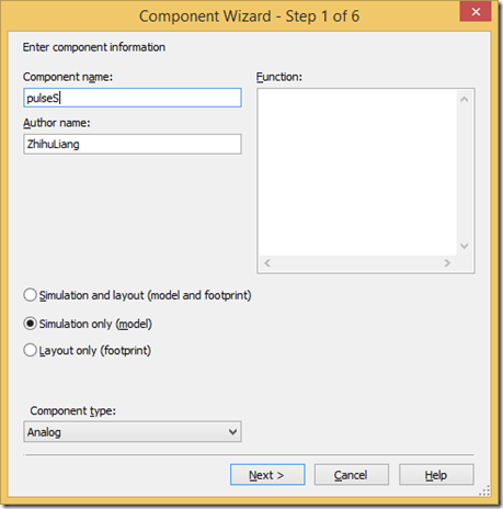
When I use Multisim Blue mouser version to simulation a circuit. I found that this version do not have a pulse source, so it is difficult to generate a pulse with delay. I found a method that could use pulse by make a component by component wizard. The steps as blew. 1) Select from menu. Tools->Component Wizard Fill the Component name as you like. Select Simulation only. Then click Button “next” Set the number of pins to 2. Then click Button “next” Click Button “copy from DB” Select Clock voltage. Then click Button “OK” Click Button “Next” click Button “Next” Fill Model Name “pulseS” and Fill Model data with: .SUBCKT pulseS CR1 CR2 PARAMS: V1=0 V2=15 TD=0NS TR=10NS TF=10NS PW=20US PER=100US vV1 CR1 CR2 PULSE({V1} {V2} {TD} {TR} {TF} {PW} {PER}) .ENDS Then click Button “Next” Then click Button “Finish”. You can put the component on where you want. When you want to change the parameter, you can right click the components and select “properties”, then click Ta...
Recently, I am designing a circuit that needs to switch off a module from 12V by a 5V control signal. So I do some research work and make desicion to use the circuit as below. The simulation result as below. The real components in the design list as below. P-Channel MOSFET: TPH1R712MD (RDSon:1.35mOhms)



评论
发表评论